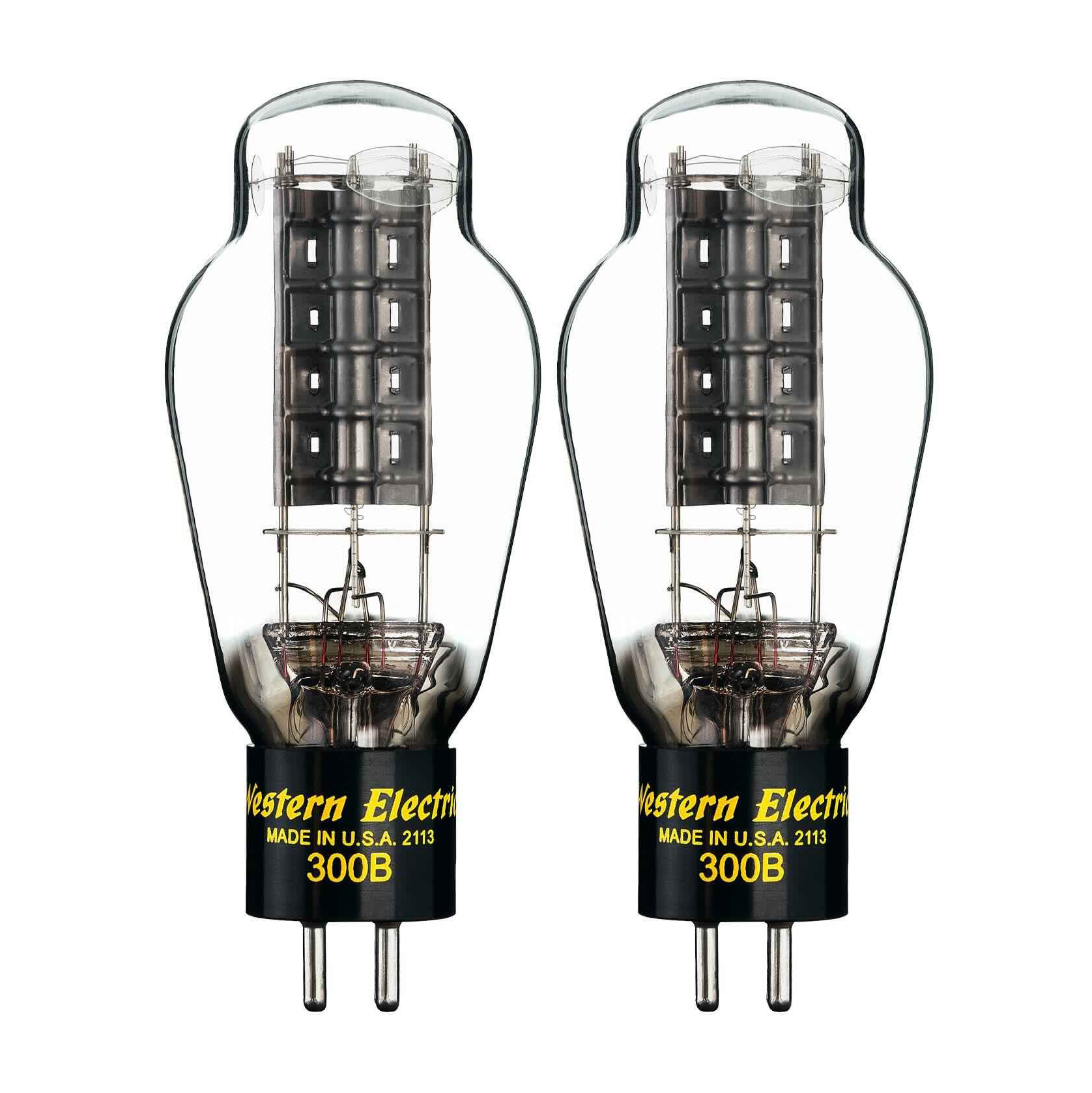
Western Electric 300B Tubes For Sale & WE 300B Vacuum Tube Specs
Western Electric 300B for sale
Single or multiple Western Electric 300B tubes for sale, available quantities: Western Electric 300B matched pair Western Electric 300B matched trio Western Electric 300B matched quad
Looking for a Western Electric 300B tube for sale? As a premier distributor of vacuum tubes since 1951, Penta Laboratories can offer an authentic Western Electric 300B replacement for your high-end audio equipment. Each Western Electric 300B tube undergoes rigorous testing at our Newbury Park facility, ensuring perfect matching for optimal performance in your 300B amplifier. We maintain strict quality control standards to ensure each Western Electric 300B tube meets the exact specifications that made Western Electric legendary in the audio world.
Western Electric 300B Tube Specs
The WE 300B represents the pinnacle of audio tube engineering, with specifications that have set the standard for over eight decades. Each tube is tested to meet or exceed these original factory specifications:
| Specification | Value |
|---|---|
| Classification | Audio-frequency amplifier |
| Power Output | 10 watts or less |
| Filament Voltage | 5.0V AC/DC |
| Filament Current | 1.2 amperes |
| Plate Voltage | 300V |
| Plate Current | 60mA |
| Grid Bias | -61V |
| Amplification Factor | 3.85 |
| Plate Resistance | 700 ohms |
| Transconductance | 5500 micromhos |
Western Electric 300B Tube Data Sheet Download
Download our comprehensive Western Electric 300B tube data sheet for detailed specifications, operating parameters, and characteristic curves. Each tube comes with individual test results and performance metrics.
Western Electric 300B Tube Substitute & Equivalent Information
The Western Electric 300B electron tube stands as the gold standard for audio amplification, though several modern equivalents exist. Compatible substitutes include the Penta PL-300B. Take a look at our Western Electric 300B tube equivalent.
Key Features:
- Balanced sound with powerful bass response
- Sweet, transparent high frequencies
- Exceptional midrange reproduction
- Ultra-long life expectancy
- Made in USA at the historic Rossville Works factory
- Individual test certification
- 6-month warranty
The WE 300B delivers remarkable audio performance characterized by dulcet tones and seductive vocals. Its plate current specifications ensure optimal operation within relatively low plate voltages, making it ideal for high-fidelity audio equipment.
Performance Characteristics:
- Rich, refined bass from the lowest registers
- Natural, emotive midrange reproduction
- Elegant high-frequency extension
- Expansive soundstage with air and space between performers
- Premium Performance: While these tubes have slightly higher plate current (B stock), they can be easily biased for optimal performance in your amplifier.
Manufacturing Quality: Each tube is produced using modernized production lines while maintaining original Western Electric standards. Our testing process ensures every tube meets the individual demands of tube making that established Western Electric's legendary status back in 1938.
As a leading electron tube distributor our technical support team are available for guidance on selecting the perfect matched set for your amplifier or for detailed information about Western Electric 300B tube applications.
Be the First to Know. Sign up to newsletter today.
